Method engineers lack a proper tool to define the construction method in larger construction projects. But what does that mean, and what are the consequences? And what is ‘construction method’? First, let’s understand some of the main characteristics of a larger construction project.
Construction method
All of us have at some point been presented instructions, whether it be to a Lego set, your car manual, or probably more likely on how to assemble your new IKEA furniture (if you actually read those instructions is another question).
To start, we can compare construction method with instructions like those. They tell the reader what to do, in which order, and what kind of tools and materials they need for specific operations. There is, however, one significant difference: While your IKEA furniture instructions might be ten pages or even 20 (if you’re really unlucky), the construction method for an O&G topside project easily amounts to some 20.000 chapters (activities) and 650.000 pages (Work orders)!
To create a construction method, the responsible team of engineers needs to understand all factors influencing the construction phase, most importantly:
-
Project execution models/Operating systems Gov. doc
-
Tender info/Contract/SOW
-
Schedule
-
Project phases
-
Capacities
-
Cost and Benefit
-
Site Need Dates
-
Other projects
-
Project EPC Coordination
-
Construction Area Disposal
-
Main Sequence
-
Facilities
-
Estimated weight
-
Transport & Lifting limitations
-
Client criteria
-
Special criteria
-
HSE/Risk
In short, we could define construction method as: ‘The optimum use of construction knowledge and experience in planning, design, procurement, production and field operations to achieve overall project objectives.’
A method engineer will typically divide a topside facility into a set of construction assemblies, considering all the previously mentioned factors.
Each of these assemblies is divided into even smaller assemblies, each with a described construction method.
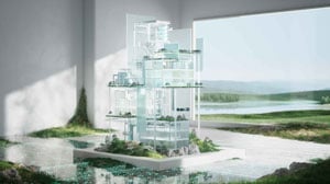
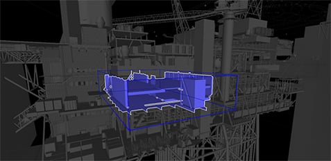 A Construction Node created in Visual Construction Planning.
Visualised and highlighted in the 3D model.
The characteristics of a larger construction project
This description references a typical O&G topside facility for the Norwegian continental shelf. With some industry specific adjustments, the same type of characteristics could be seen as general for any larger construction project in any industry.
The illustration below highlights numbers from a reference project very similar in size to the NOA PDQ topside:

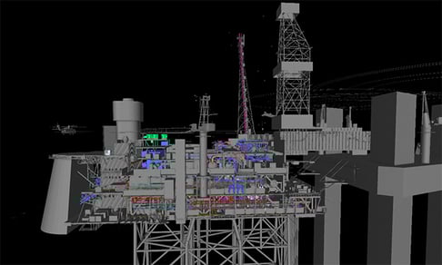
A 3D visualisation in VCP. Connected to the drilling Platform on the right.
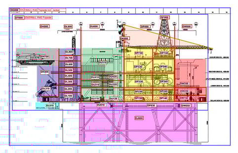 Topside as a 2D drawing defining the AREA definitions and stating the Naming Conventions.
So from a construction perspective, what is the story here?
- There are more than 700.000 physical pieces in the puzzle. This number says something about scope size and the person-hours required to assemble, and not least verify, that all components are functioning and have been fabricated and installed in accordance with requirements.
- The construction of these more than 700.000 physical objects needs to be planned in a logical sequence. The project planners' responsibility is to understand the construction method and derive an optimal plan. It will take more than 22.000 activities (read lines in a Gantt chart) to finish the construction. More than 680.000 work orders have to be defined and handled by the construction organisation to execute these activities. These work orders must be sequenced and monitored for progress and person-hour consumption.
- The construction activities are carried out at a large number of construction sites. There are sub-contracts for certain parts of the construction scope; other sub-suppliers deliver equipment and different scopes of final assembly sites. This paints the picture of a complicated material logistics operation where steel and every other item you need must be at the right location at the correct time and in the correct quantity to avoid delays.
- The total construction scope is enormous. A very limited number of construction yards can build constructions of this magnitude from scratch in one operation. That’s why we need to divide the scope into sub-assemblies so we can optimise the construction phase based on all the different factors mentioned in the ‘method engineering’ section above.
Adding to this complexity: The engineering, procurement and construction phases are not sequential. They very often overlap to reduce the total duration of the project. A natural consequence is a need for coordination.
Engineering needs to complete the design of the first planned construction scope (based on the construction method), and procurement needs to secure this material first to the correct yard at the right time. Engineering and procurement activities can run into changes, delays, or other challenges that push them out of alignment with the construction team’s plan and progress. If this happens (or perhaps when it happens, as it is very difficult to avoid without tools like VCP), it could quickly lead to increased cost in the construction phase as work needs to be performed out of the optimal schedule.
Current state problems
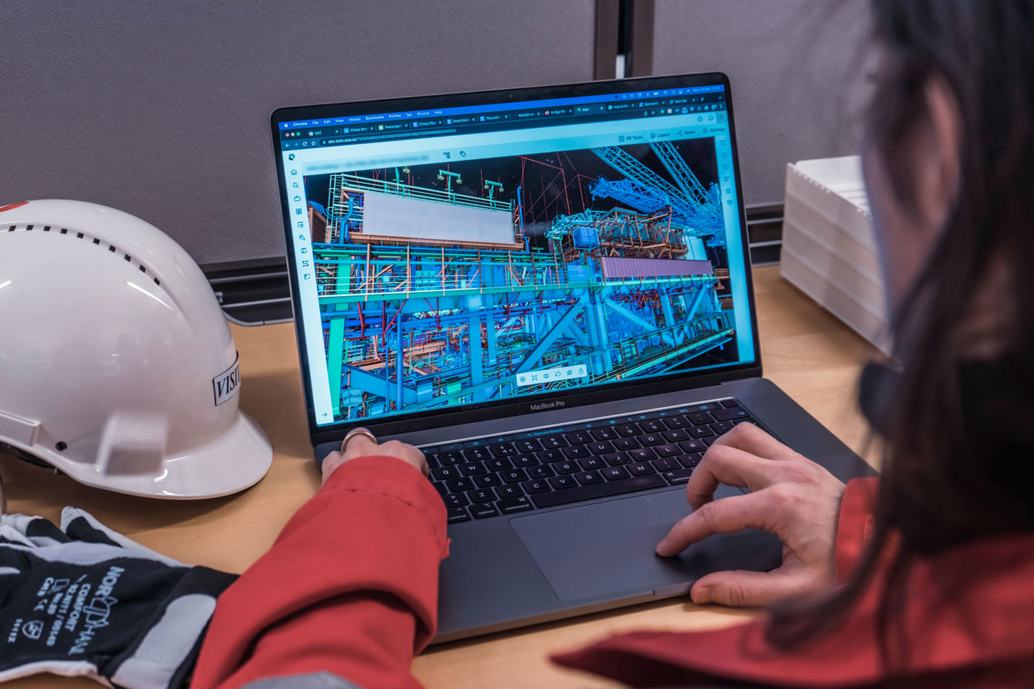
So, we’ve stated that method engineers don’t have the proper tools to define the construction method. So how do they do it? The short answer is by using traditional office suite applications and screen grabs from any 3D model they can find capable of visualising what they need to convey the construction method. The illustration below pinpoints this problem: Documents are subject to revisions, archiving issues and are difficult to keep up to date. These are the obstacles to a single source of truth where the entire project (EPC) can find the latest construction method - and trust it.
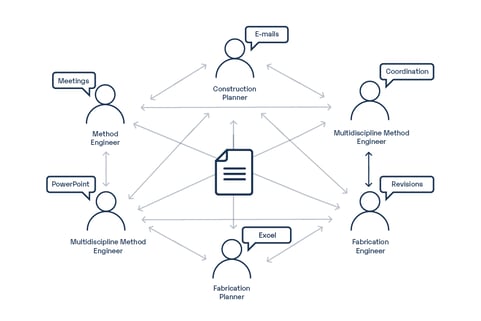
The communication flow can be fragmented across different channels where it can be difficult to understand what the latest version of anything really is.
This increases the risk of misalignment, where the intent of the construction method is misunderstood or simply outdated. And when the EPC is in a situation of misalignment, it increases risk. Also, out of sequence work in construction is most likely already occurring.
As the construction method is document-based, its corresponding plan is manually derived to a high degree. This is a time-consuming activity for project planners, and it is easy to understand why the resulting plan doesn’t always align 100% with the construction method’s intention. This can have similar effects as the mentioned EPC misalignment: Construction work has to be performed outside its optimal sequence or with other constraints that reduce productivity.
These are the two pivotal issues visual construction planning aims to improve:
- Optimising the collaboration between method engineers, project planners and design engineers;
- Improving accuracy in construction planning and reducing the person-hours needed to create and maintain construction plans.
The solution - Aize and its visual construction planning
So, we’ve seen how construction method is essential in understanding how construction is executed. Visual construction planning in Aize allows method engineering to be done in a 3D tool simultaneously and aligned with design engineering, ensuring a well-bridged E and C (as in EPC).
The result: A design that incorporates the intent of the construction method and minimises the possibility of misalignment within the project.
Aize provides method engineers with a proper tool for optimising the discipline with a better and more efficient way of working.
In addition, construction planning is optimised, gaining efficiency and increasing quality by making sure the construction plan is well anchored in the construction method - which again minimises the possibility for misalignment within the project.
When we assure better alignment in EPC - founded on the construction method - we reduce the risk of out-of-sequence work in construction. We set the construction team up for success by executing all planned activities in the correct phase. In larger EPC projects, this can significantly affect the bottom line. This is where we find the most savings in a VCP business case.
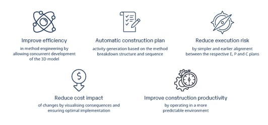 The high level gains with visual construction planning, where the improved construction productivity is the major key factor.
Do you have any questions?
We would love to hear from you. Feel free to reach out to us at any time.